
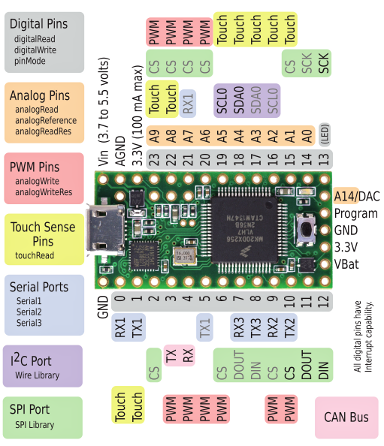
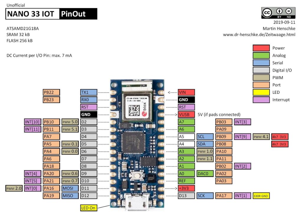
Maybe it is because many of the pinout diagrams for the Nano have SCL and SDA on the wrong pins.
You probably think (as I did and as the guys laying out the pinout diagrams) that these would be on digital pins, but they are not. They are on analog pins.
SDA              Pin A4
SCL              Pin A5
Once you wire it up correctly, this arduino I2C scanner will let you know you have proper connectivity and the address for the device:
http://playground.arduino.cc/Main/I2cScanner
Jump to Pinout for:
Here is a correct Nano pin out diagram:

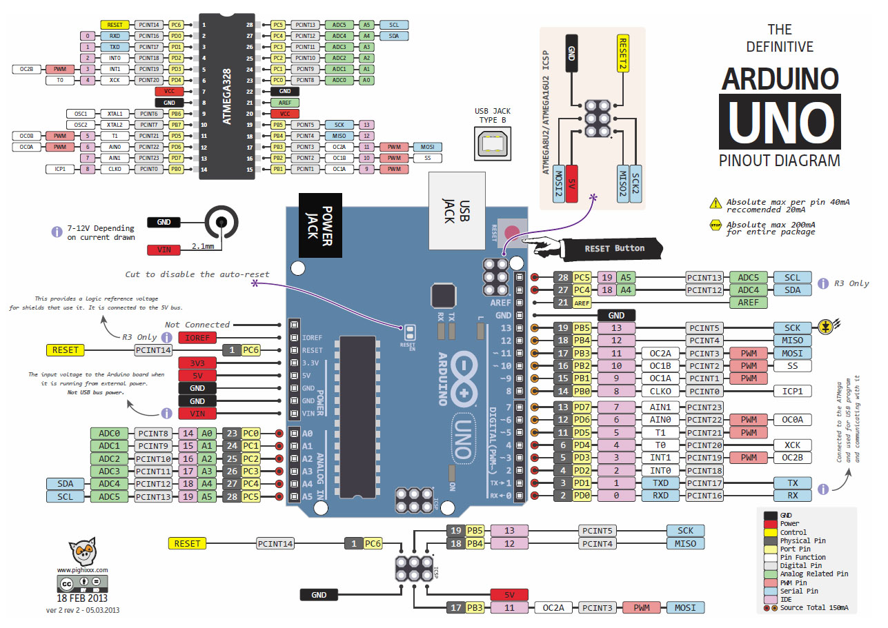
And while I’m at it, here is one for an Uno:


Thanks for posting the pinouts! I was going to tediously go through the whole thing and map them out myself but no need now.
Saved on the hard drive for later reference
These pictures are awesome – I wish you had provided a key as to what the labels means. I’ve deduced most of them on the Nano (EG. wiggly line means PWM enabled on one of three timers and pale-blue is a type of serial IO) but others (EG. Yellow circle and white square) ellude me
A more detailed Nano pin out with a legend can be seen here: http://pighixxx.com/nanopdf.pdf
That’s fantastic! Many thanks.
Awesome thanks mate and keep up the excellent work! – saving us lots of frustration 🙂
This is amazing ! Beautifull & usefull pinout diagrams !!!
what software it was used to do all of them, by example Arduino Mega’s?
you know it?
I want to do it myself 🙂
thanks!
Good for quick reference! 😉
Great job. very useful. LIKE !!
WOW, that is what I am looking for! Awesome overview! THANKS!
This helped me out. Thanks a lot
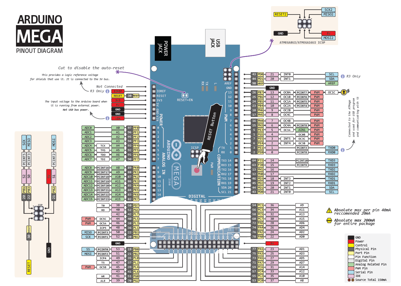
Fig. Arduino MEGA is incorrect pin INT0 – INT5. see https://www.arduino.cc/en/Reference/AttachInterrupt
I think you are misreading. The arduino doc you mention indicates interrupts on pins 2, 3, 18, 19, 20, 21.
If you look at the IDE pins in the diagram (kind of a pink color), you’ll see interrupts 0-5 are assigned to pins 2, 3, 18, 19, 20, 21.
If that is wrong, please explain. Thanks.
Hi Dan,
I checked what ARD2560 said about the interrupt pins and he appears to be correct. You have them marked in the wrong order. It should be:
Pin2 – Int0
Pin3 – Int1
Pin18 – Int5
Pin19 – Int4
Pin20 – Int3
Pin21 – Int2
This is based on:
https://www.arduino.cc/en/Reference/AttachInterrupt
Paragraph “Interrupt numbers”
OK, I at least see the original complaint now – the reference you are looking at says Pin 2 should be interrupt 0. I don’t have time to try this myself, so I tried to find additional sources that agree. Unfortunately I can only find the original diagram I posted, the arduino.cc reference you mention, and this pin mapping diagram (https://www.arduino.cc/en/Hacking/PinMapping2560) which agrees with the picture not the reference. Have you tried using interrupt 0 on Pin2 on a mega and can verify the reference is correct and not the diagram or pin mapping diagram?
It’s not my diagram so I can’t (well won’t) change it, but if it is correct I will stick some commentary before it.
I mean the assignment of interrupt number to dig.pins , Mega2560:
INT0 INT1 INT2 INT3 INT4 INT5
http://www.arduino.cc…: 2 3 21 20 19 18 – see tab. down
bigdanzblog.wordpress…: 21 20 19 18 2 3
(I am sorry, I use Google Translate.)
You forgot OC0B on pin 5 (PD5) of the Arduino Uno.
Sometimes it’s not a pin out problem. I have an barometer sensor can run either 3.3V or 5V.
When connected to 3.3V on Nano it does’nt work but on 5V. I’ve checked 3.3 voltage is OK.
On Uno board however it works from 3.3V Pin.
Thanks for those amazing pinouts
Pingback: 【Arduino】LCDディスプレイを使ってみた – A hint of smart agri
Thank you. Thank you. Leave it to me to have this by my first board I’ve worked with. I of course resoldered all my connections thinking that must be the problem. Who’d have thought the board would be incorrectly labeled. One more notch in the challenge belt. Thanks again!
Pingback: A DIY Drone Remote Controller | Manohar Kuse's Cyber
Pingback: Atmega328 - Home Floor Plans Architecture Ideas
Pingback: Making a Light Alarm Clock with Arduino + RTC for Beginners - Wintermute Digital
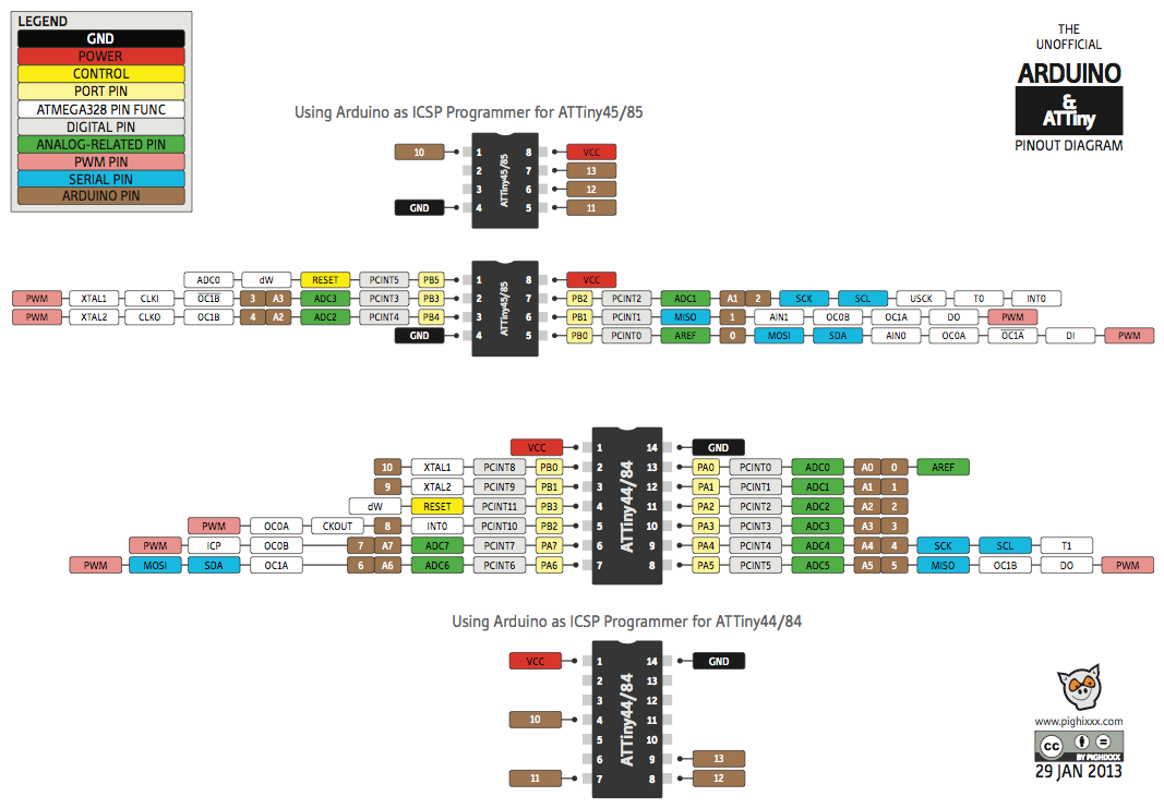
Attiny 84 you have posted WRONG pin map, i have lost a lots of time trying to make it work, then troubleshooted pins, it is going anti clockwise (0-10), and i was relieved when i found confirmation here: https://forum.arduino.cc/index.php?topic=211843.msg1554336#msg1554336
I am unable to tell from that link exactly what the problem is, but I’m looking at ATMEL’s data sheet and the labels they use are in the same place on the JPG. Tho there are more labels on the JPG than the datasheet, and I cannot verify those.
Well i actually verified and tested it myself, so i posted that just as resolution. Bottom line pins you posted on image http://www.tr3sdland.com/wp-content/uploads/2013/02/ATtiny.png regarding ATTINY84 are wrong (shuffled), exact pins are in the post i shared link to (verified trough coding suffering and troubleshooting) i was shocked how well made nice picture that is factually WRONG is shared all over the net!
If it does not work despite using correct pins, try using a pullup resistor (I used 4.7K) on both pins.
Pingback: Makeblock XY 绘图仪上的grbl? | GRBL官方网站
Pingback: grbl on the Makeblock XY Plotter? #872 | GRBL官方网站