
I’ve built a project using a SIM900 GSM/GPRS dev card. It works fine, but that dev card is too big to fit in the project case and kind of expensive (comparatively speaking).
I went looking for another solution and found the SIM800L:

Looking thru the manual, it supports all of the AT commands I implemented on the SIM900 in my project. It is also quad-band, so it should work in the U.S.
I found a SIM800L dev card on ebay for $10 so I bought a couple. The downside was it came from China and took a month to get here. Much slower than most of the stuff I have purchased from China in the past.
Documentation
This schematic seems to match up with the particular SIM800L dev board I have:

The SIM800L Datasheet:
Click to access SIM800L_Hardware_Design_V1.00.pdf
and the AT commands:
Click to access sim800_series_at_command_manual_v1.01.pdf
Getting It Running
The first thing I wanted to do was get the card connected to my PC so I could verify I could access it, then make sure that it works with my cellular carrier. To do this, I connected the SIM800L dev board to a standard 5V FTDI cable such as:
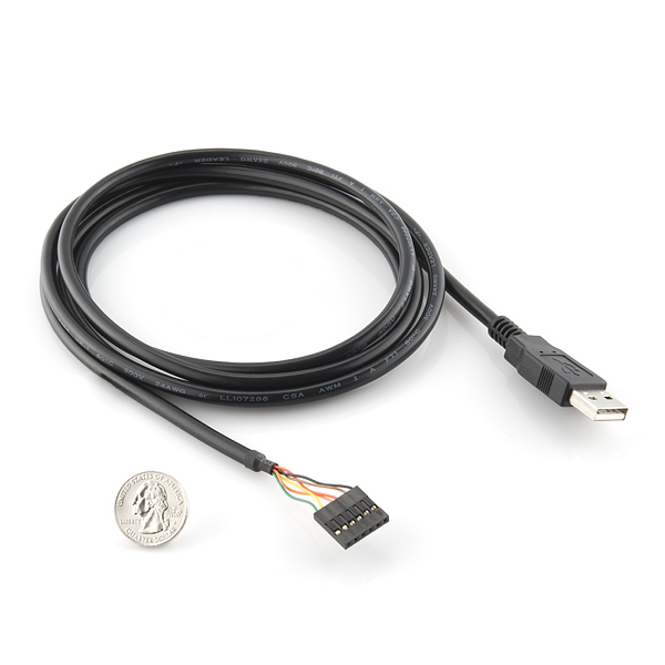
https://www.sparkfun.com/products/9718
I am using a 5V FTDI cable. The dev board needs 5V and the tx/rx lines are 5V tolerant.
Connecting the cable to the devboard is very simple using male/female jumper cables:
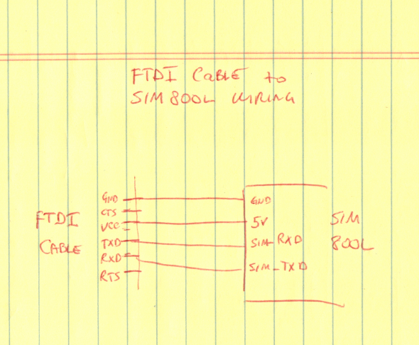
and here is the final test setup:

If you’ve not used an FTDI cable before, it needs drivers. I believe in Windows 7 and on these will be located automatically. If not, the provider should make drivers available to you.
Once the cable is plugged in, you should see RING diode light continously and the NET diode will flash.
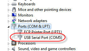
To connect to the dev board, I am using putty. First I need to determine the COM port that was assigned to the FTDI cable which can be found in the device manager:
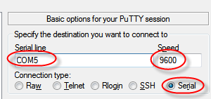
Now start up putty, select Serial for the connection type, enter the COM port from device manager, and speed is most likely 9600 baud:
Type AT and press enter (the first time I do this, I don’t see the AT echo back). Once you press ENTER, you should see the AT followed by OK.
If you don’t get anything, make sure the wires between your TX/RX lines are correct. Tx goes to Rx and vice versa. If you see garbage, chances are you need to try a different baud rate.
Once AT by itself works, I tried a few other commands to verify operation:
AT+CGMM
SIMCOM_SIM800L

AT+cgmr
Revision:1308B08SIM800L16

AT+CPIN?
ERROR
AT+CPIN? is supposed to report SIM card status. Since it hasn’t been installed yet, I guess this ERROR is OK.
Obtaining the SIM Card
To make this device work, you will need a functioning GSM SIM card. Fastest way to take care of this problem is to go to a store and get a pay as you go SIM card. If you don’t have a phone that can make use of that card, you might want to pickup a cheap unlocked GSM cell phone for testing as well.
My normal carrier is a GSM carrier (AT&T, T-Mobile, or any of a host of other carriers that use AT&T or T-Mobile’s networks). I can request an additional line and they just send me a free SIM card. I pay $10 / mo for the additional line and it shares my existing data/text plan.
As already mentioned, it is easier to activate the SIM card if you put it in a phone first. Once you can place calls/texts on the test phone you are sure the SIM card works and any problems you might encounter will not likely be due to the SIM card or carrier.
Inserting the SIM Card
The SIM card is inserted with the contacts towards the PCB and the notched end sticking OUT!

Now the SIM card status command returns ready:
AT+CPIN?
+CPIN: READY
The AT+CNUM reports the correct phone number:
at+cnum
+CNUM: "","1xxxyyyzzzz",129,7,4
AT+CSQ reports roughly 50% signal quality (max is 31):
AT+CSQ
+CSQ: 17,0
Obtaining Current Time
By default, the SIM800L is not set up to track time status messages coming from the carrier. So if you request the time via AT+CCLK?, it will be wrong. To fix this, type these commands:
ATZ
OK
AT+CLTS=1
OK
AT&W
OK
Now cycle power on the SIM800. If you connect to the serial port fast enough, you’ll actually see the time ‘commands’ coming from the carrier:
AT
OK

Call Ready

SMS Ready

+CTZV: -28,1

*PSUTTZ: 2016,3,26,17,49,24,"-28",1

DST: 1
and now if you request the time, it will be correct:
AT+CCLK?
+CCLK: "16/03/26,10:49:36-28"
Using the RESET Pin
There are 2 downsides to the SIM900 DEV board I have – it will not come up without you manually pressing the POWER KEY and there is no way to force it to reset. Supposedly there are ways to solder connections to handle these issues, but that is still a bit clumsy.
The SIM800L holds the POWER KEY on for you so as soon as it gets power it is running. That is what I need for my project.
The next question is how does the RESET pin work?
Like one would expect – I grounded RESET and it forced the SIM800L to restart. Perfect!
Apr 2016 Update:
I purchased 2 of these to use in a project. They are both so unreliable they are worthless. Regularly they reset. This is an indication there is not enough power – they need 2A of clean power. Well, I have put them both on a 5A bench power supply and still have issues. Further, I followed the datasheet regarding filtering and that didn’t help either.
I’m trying a simpler board next (no onboard power circuitry nor a reset pin) to see if I can make it work. If it is any better, I’ll post an update.
Yep, much better luck with a different board. Click here to see it.


Pingback: SIM800L GSM/GPRS Part II – Seeking Stability | Big Dan the Blogging Man
hi
Thank you for your helpful training
Please Put your Codes send SMS for Arduino DUE .
is there any way to fix the variant you have above? i have the same issue – these things from china arrive incredibly slow
I had no luck with the original model I purchased, but the one that worked I got from amazon and it arrived pretty quick – being shipped from the U.S.
They are really sensitive to power availability and power noise. You might try using a properly sized lithium battery for the interrim.
Yep, thanks very much Dan for the info.
Same here. The module is an overstated piece of doodoo!
ok, it is good article, it can help me。CNC Machining
HI
I´m trying to use the SIM800L from a Terminal program and a proper TTL interface, and I´m leaving the RST pin free …
There.s no problem … the green led blinks almost second or so … with commands like AT … ATE0 or ATE1 or ETZ … and even AT+CGMM … everithing is ok .. but trying commands like
AT+CPAS or AT+CSQ and a lot more the modem response is always ERROR … Could you please tell me what I´m doing wrong.
Thank you very much.
Since the basic AT commands work, you obviously the serial connection working.
My guess is there is something wrong with your GSM connection. I vaguely recall having some problem like this as well.
I believe my problem was I originally purchased a SIM800 card which doesn’t use the proper frequencies to operate in the U.S. and none (or at least some) of the GSM commands wouldn’t work. I purchased an SIM800L which uses the correct frequencies and it worked fine.
The other possibility is your carrier doesn’t support 2G GSM (second generation). In the U.S., AT&T retired their 2G network in Jan 2017 I believe it was. As soon as they did, my SIM800L project stopped running.
The only U.S. carrier left supporting 2G is T-Mobile. I got a SIM card from them, stuck it in the SIM800L and I was up and running again.
Hopefully that will give you a clue where to look for the problem. Good luck!
Dan
salve, sono Stafano, anche io ho avuto il problema con la Sim800L, si resettava in continuazione, dopo una estenuante ricerca senza alcun risultato, quasi scoraggiato e sul punto di mollare, mi sono messo con santa pazienza a studiare il circuito e con un tester ho iniziato a monitorare i vari step dell’ alimentazione……alla fine ho trovato che il diodo 3 aveva un enorme calo di tensione, da 5v che fornivo in ingresso arrivava a 3 ed anche punte di 2,4v… la soluzione è stata di bypassare il diodo 3. Ora funziona perfettamente senza manifestare alcun tipo di anomalia
Here is google translate of above:
hi, I’m Stafano, I also had the problem with the Sim800L, it reset itself continuously, after an exhausting search without any results, almost discouraged and about to give up, I started with holy patience to study the circuit and with a tester I started to monitor the various steps of the power supply …… in the end I found that diode 3 had a huge voltage drop, from 5v that I supplied in input it reached 3 and also peaks of 2.4v .. the solution was to bypass diode 3. Now it works perfectly without showing any kind of anomaly
HI Stefano,
the diodes are required to reduce voltage at SIM800L IC (a better approach would have been a 5V-3.3V linear regulator). Max voltage at IC pin is 4.4V as per datasheet. So, 5V direct might work for some time, but risks to burn the device.
Reset problem is fairly solved by soldering an electrolytic capacitor of some hundreds uF at 5V-GND connector pin.
Usually some cm long cables to the power supply cause inductive drops in the supply voltage when TX current is required, generating voltage dips that cause reset.
I hope this helps.