
I recently ordered a WWVB receiver from CanAduino. This breakout board allows you to receive date/time transmissions from the WWVB radio site in Fort Collins, CO. I have kind of an idea I might use this for future projects needing accurate date/time when other methods are not available.
An explanation of WWVB can be found here.
The module showed up with no documentation. Going to their site, there are a few documents:
- Bruce Hall’s WWVB Clock
- Detailed datasheet for the MAS6180C receiver IC
- CANADUINO WWVB Atomic Clock Receiver Kit (V2)
Note there is no documentation for V3 of the board. They say V3 changes are small enough not to warrant a documentation change.
You can only see the schematic of the breakout board thru a little view port. I can find no way to get a full size image so I can easily examine what is happening.
While looking at reviews on Amazon, hoping to find more basic info, I found someone complain they had trouble installing the crystal. Weird, I didn’t notice a crystal. There was one and it was so tiny it had fallen out of the bag and I never saw it. Luckily I was able to find where it had rolled away to.
I’ve purchased various Raspberry Pi’s and parts from CanAduino before without issue. I’m surprised this device wasn’t a little better documented for beginners. Or maybe they thought this was too hard for a beginner??
Assembly is pretty straight-forward. I stumbled thru the process and I’ll share what I did below. My only real flub was to not position the crystal properly leaving it to touch another pad. Wiring and testing is also pretty easy and was documented by Bruce Hall. I will summarize that in this procedure as well.
Assembly
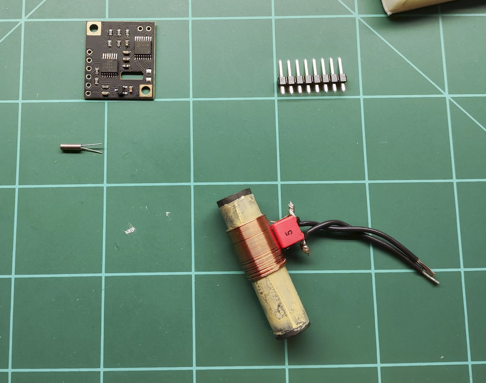
You should have the following components: the breakout board, 8 header pins, a crystal, and a ferrite antenna:
Soldering Crystal to the Breakout Board
The breakout board works with different radio transmitters, each with its own frequency. The NIST radio station near Fort Collins, CO (WWVB ) as well as the ones in Japan and England transmit on 60kHz so you will install a 60kHz crystal (supplied). If you intend to receive a different station you would need the appropriate crystal.
This crystal is quite small. One reviewer on Amazon mentioned that he had a lot of trouble soldering the crystal leads to the pads as there wasn’t adequate solder on the pad. My technique should help alleviate this problem.
First, I placed the breakout board into a vise to hold it steady. For this job, I used my stickvise.
The crystal is NOT polarized so you can connect either lead to either pad. Using blue masking tape I carefully positioned the crystal. Make sure the crystal sits roughly in the cutout. It can come into contact with leads for one of the ICs on the PCB if you aren’t paying attention.

Before grabbing my solder iron, I used a dental pick and practiced how I would grab and hold the lead against the pad while it is being soldered. If you don’t have a dental pick I strongly recommend one – a whole set is pretty cheap on amazon. I don’t use it often, but I’m glad I have it when I need it to manipulate really small parts.
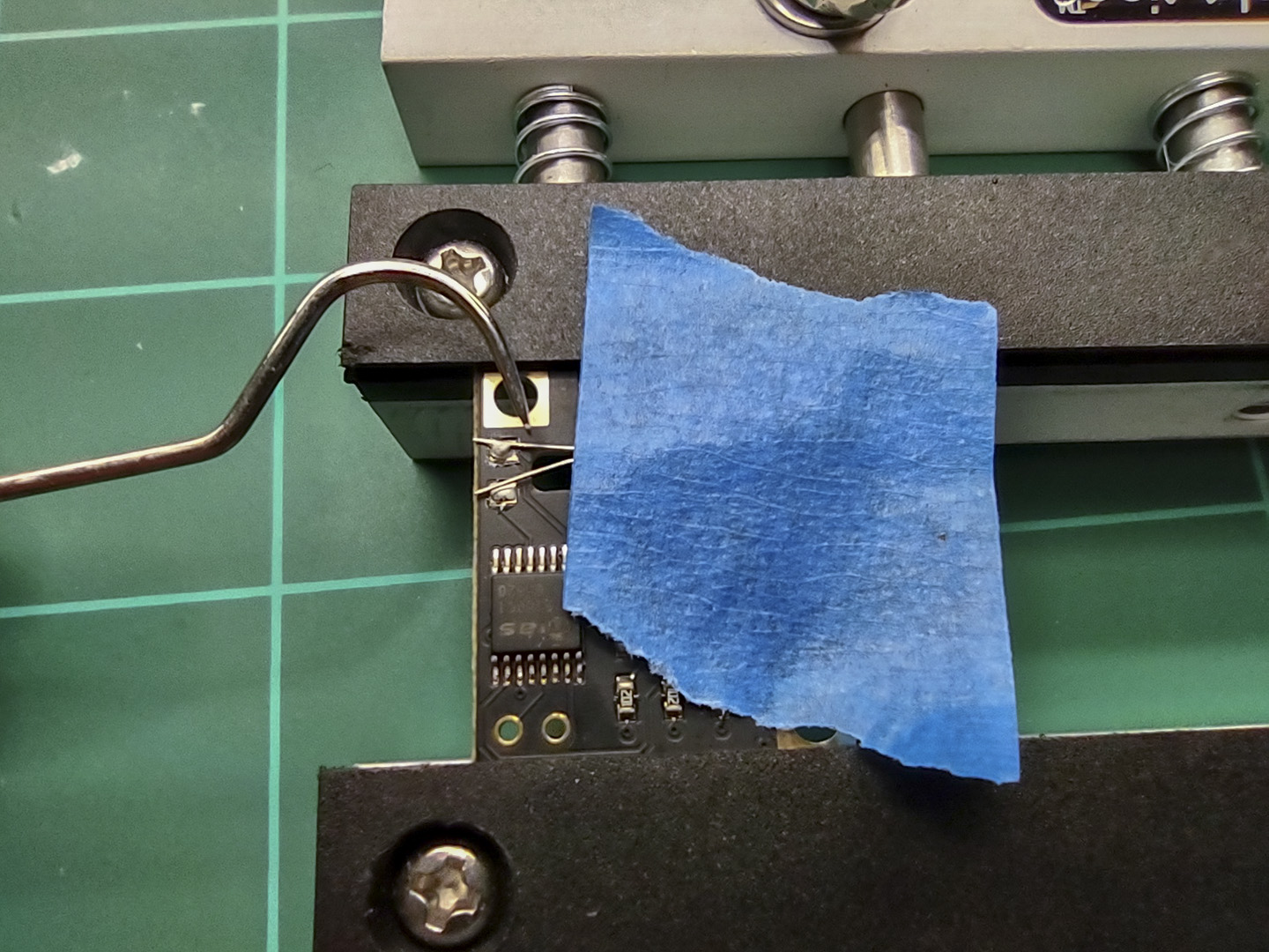
As you can see, there is already some solder on the pad. When you are ready to solder the lead, touch the tip of your solder iron to your own solder so the tip isn’t completely dry – that should give you enough solder to complete the job.
With the solder iron and dental pick ready to go, positioning and soldering the lead was pretty easy. Not pretty, but I got the job done:

Attaching the Antenna
The antenna presented a bit of a conundrum. First, the leads are too big to fit in the PCB. I saw one guy soldered his antenna’s leads to 2 header pins and soldered those to the PCB. Workable, but I decided I wanted the option to remove the antenna and perhaps extend it a bit. So I decided to crimp on female dupont connectors. I’ve covered this procedure before.
Note that the insulation will not fit into the crimper, but the bigger tabs crimp around the conductor just fine.

Solder on Header Pins
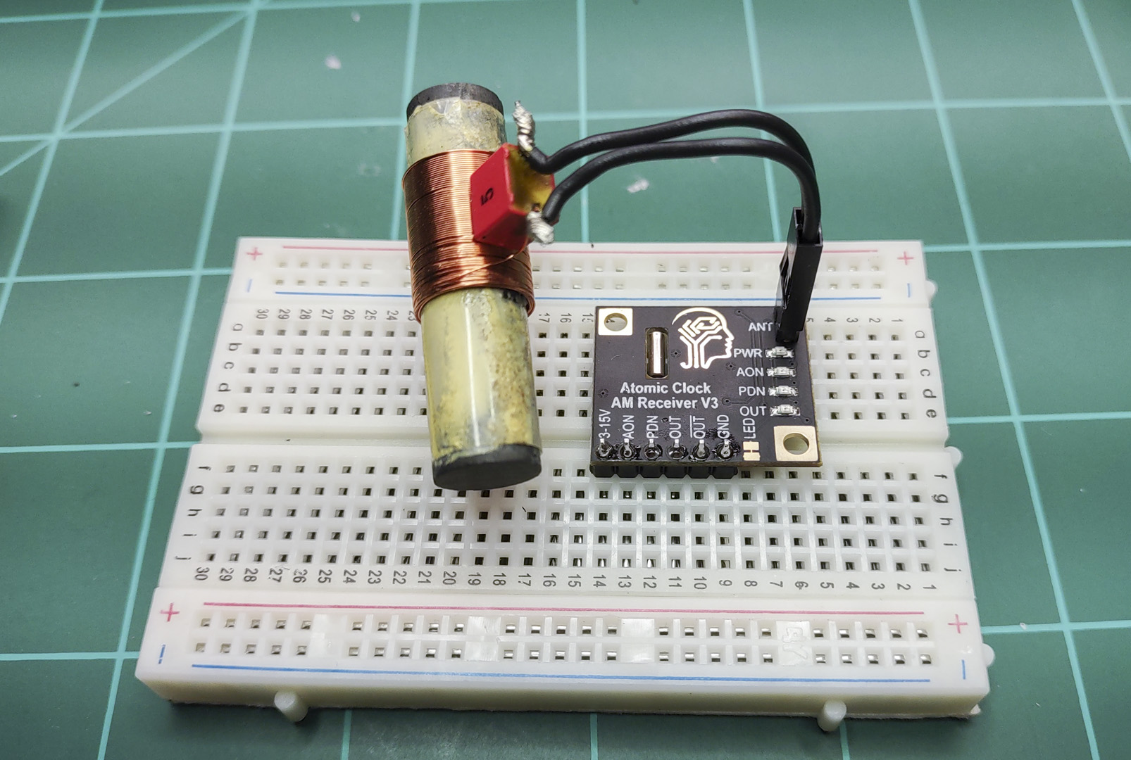
After snapping 6 pins carefully off, I placed the header pins into a breadboard and then soldered the PCB to them.

The final assembly looks like this:
Wiring
The module can support 3-15V. I happen to have a 9V battery that can be quickly connected to a bread board making this project mobile so that is what I used. I was pretty sure I was going to want to walk around testing and I was right.
For testing, wiring is very simple:
Pad Name                          Connection
3-15V                             +9V
AON                               Unconnected
PON                               GND
OUT                               Unconnected
BAR(OUT)                          GND
GND                               -9V

Testing
I live on the West side of the Rockies at least 700 miles from Ft. Collins. The “atomic” clocks inside of my house usually will only detect WWVB after dark, so I expected to have some issues with connectivity.
When you power up the breakout board, wait for the OUT LED to turn on. It can take as long as several minutes. Once the OUT LED lights, you should start seeing it flash.
About every 10 seconds, WWVB transmits a 800ms MARK which will cause the OUT LED to turn off for 800ms. If you have a good connection you should be seeing these MARKS.
When I have the unit on the east side of my house, with the antenna perpendicular to about where I think Fort Collins should be, I see the OUT LED flicker and fully extinguish periodically. When I go to the west side, the OUT LED is almost on solid. Just very short flickers. Chances are that is a bad signal.
If you don’t have a good signal, go outside. If it is still bad, try again later after dark. Here is a coverage map showing signal strength at different times.
My last step was to connect the breakout board to my Teensy 4.1 ‘Dev’ board I built this spring so I am ready to start reading data. I’ved tested with both 5V and 3.3V and the breakout board powered up fine. I will be using a USB battery pack for testing so I can move the whole assembly outside, at night, if necessary during testing.

Nov 2023 Update
I have written code that has successfully decoded the WWVB signal. It will be a while before I will get the chance to make a generic version of the code to make available. Until then, I have a couple of notes worth mentioning ahead of time.
First, in the picture of the breakout board above, connected to my little Teensy 4.0 dev board, you see long jumper wires. Specifically, you may notice that the 3.3V wire runs right next to the antenna. After spending days trying to understand why I could never get a good enough signal to decode even one packet, I found that those long jumper wires were causing interference.
Once I got the jumpers away from the antenna, my reception improved quite a lot and I managed to decode 7 packets that first night between about 12AM and 2AM.
Here is the rewired breakout board:

Further, my original explanation of what a good signal looks like is not very helpful. The OUT LED really doesn’t flicker. It should go to the OFF condition at .8, .5, or .2 second intervals. There should be minimal fast flickering – that indicates a poor signal. I took this video during the time I was getting maximum WWVB signal strength. The focus sucks – the board is in an awkward location where I expect to get the strongest signal. But you can see the OUT light flashing as an example.
Here is a trace of the OUT pin from the breakout board on an oscilloscope:
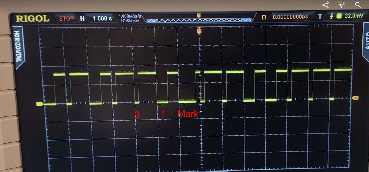
A ‘0’ is a LOW signal for 0.2 seconds. ‘1’ is LOW for 0.5 secs, and ‘MARK’ is LOW for 0.8 secs.


Pingback: WWVB Atomic Clock Receiver Driver for Teensy 3/4 (MAS6180C) | Big Dan the Blogging Man