
 I’ve been working (for way too long now) on a development platform for future projects using a Teensy 4.0. A few weeks ago I was finally to the stage of creating the PCB.
Initially I planned to power the project with a 5V barrel plug as I’ve done in the past. Then I thought, why not also include a Micro USB socket since I always have those power supplies laying around. On this DEV board, I made both present so I could choose between them.
This was one of those last minute decisions which was not well thought out. I found the component I wanted on mouser which had a foot print available for Kicad. I designed the PCB without actually seeing the component. I had worked on this for so long I wanted to get the PCB ordered without waiting to see get the actual component in hand.
Its not like I’ve never seen a Micro USB socket before, but when I finally got them in the mail and looked at the size of the pins, my thought was “OH WOW how am I going to solder that???”
An alternative could have been a Micro USB breakout board such as Adafruit’s product #1833:

And, in fact, I may very well go back and add that footprint to overlay the existing footprint I used so I can use which ever I like.
But that doesn’t help me now. I’ve got 3 rather expensive PCBs of this design from OSH Park to use for now.
I went looking for help on soldering a Micro USB socket to a PCB and there is really not much help. The most apropos help came from StackExchange. Combining the advice I came up with a solution I thought most likely to work for me.
First, I was going to need some solder paste which I purchased from Amazon:

I also needed fine tweezers, flux paste, and isopropyl alcohol which I already had.
Flux and Solder Paste
 The first step is to apply flux paste liberally to the footprint using a cotton swab. Then came the first tricky part: applying the solder paste. I have only soldered SMD components two other times in my life so I don’t have a good idea of how much to use.
First, I experimented applying a bit of solder paste to a piece of paper until I was sure I could control the flow. Once you squeeze to get the flow going, you then need to retract the plunger to stop the flow so you don’t get too much on the pads.
I figure given how tiny the pins are there is no reasonable way I’m going to be able to control the paste flow well enough to solder the pins. Instead, I simply put small dabs of solder paste on the component mounting pads like this:
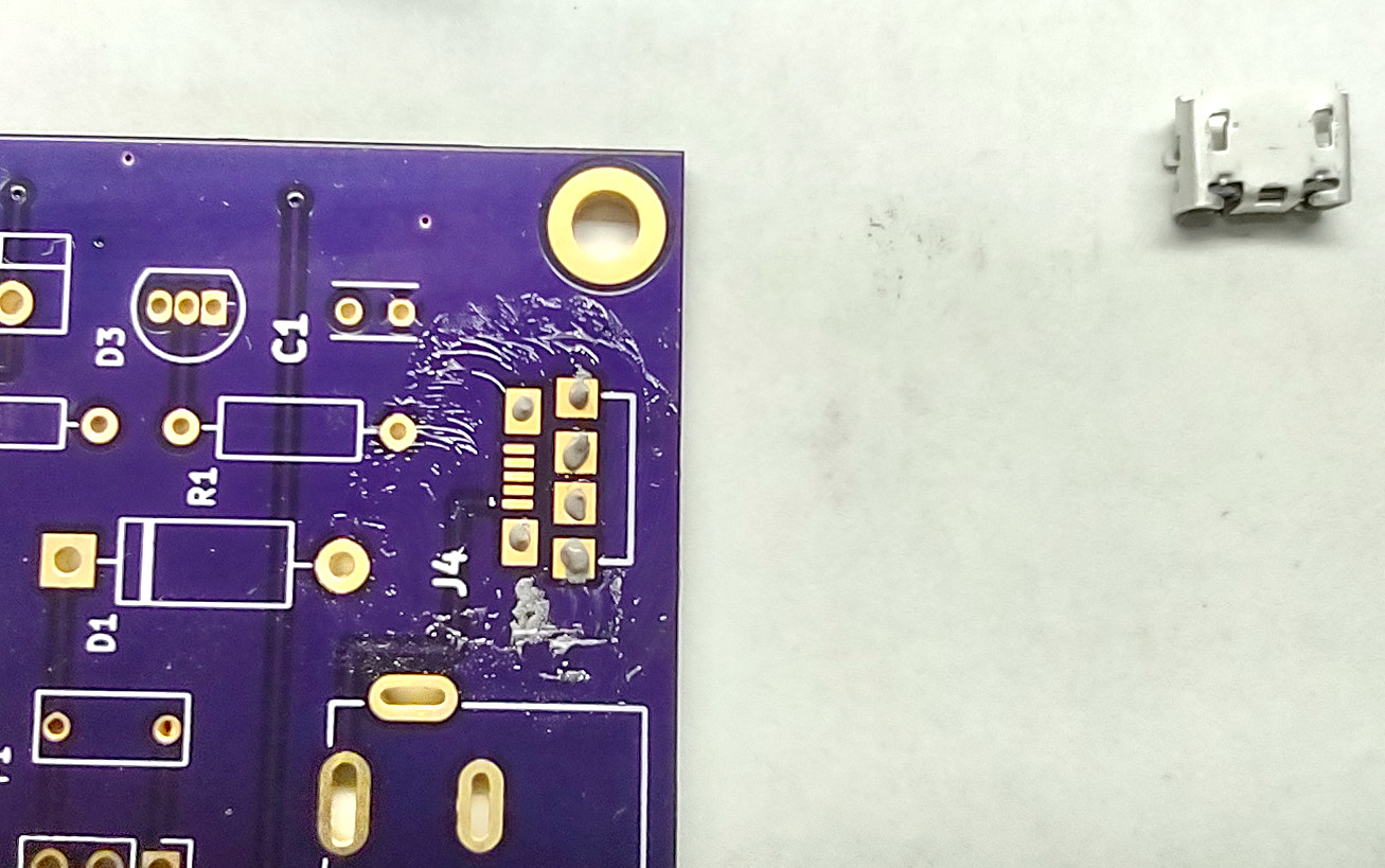
If you look at the above picture closely you will see some solder smeared below the footprint. I got too much on the pad, used an exacto knife to remove it from the pad. A little was left behind. It didn’t seem to cause any issues.
Placing the Component
I took the whole assembly out to the garage to apply heat. I taped a cardboard box to the work bench and the PCB to the cardboard box (in retrospect, perhaps a cardboard box wasn’t the best solution).
Then using my shop magnifying light, I placed the MicroUSB as close to where I thought it needed to go. But that magnifying glass just didn’t have enough resolution to verify the pins were aligned to the pad.
I ended up using a flashlight and the inset magnifier on this magnifying glass to be able to verify I had the component in place.
 With the USB socket in place, it looked like this:

Heating the Solder Paste
With everything in place, I fired up my trusty old heat gun on low and faced it straight down onto the board. I didn’t want to use high and risk nudging the component off the footprint.
 If it took 30 seconds for the solder paste to melt, that was it. You could see it suddenly go from from dull grey to bright silver. Once I saw the transition, I held the heat gun there for another 10 seconds to be sure the solder on the pads below the component melted as well.
Once the PCB and component cooled, I used alcohol and a cotton swab to clean as much flux off the PCB as I could. Here is the result so far:

I tugged at the component to make sure it was reasonably well fastened to the PCB.
Soldering the Pins
Now for the really tricky part. As previously mentioned, I didn’t figure I would be able to apply solder paste thinly enough to solder the pins to the PCB. Instead I will use what is know as the swipe method. I will just run a solder iron with some solder on it across the pins.
First step was to install the finest solder tip I had onto the solder iron:

Then I used a cotton swab to apply flux paste liberally to the pins. One comment I read somewhere is to use leaded solder for this swipe technique. So I broke out my ancient spool of radio shack solder.
I cleaned the hot solder tip well (I’m using 750F), then applied just enough solder to see a bit of a bulge on the tip. I then ran the tip fairly quickly across the leads. Without checking my work yet, I then heated some copper braid against the pins to suck up the extra solder.
 Now I carefully examined the pins with a flash light and magnifying glass. I could see all of the pins were bright sliver except the ground pin. I repeated the process again to make sure the ground pin, too, was soldered.
The second attempt appeared to be successful. I could see bright solder on all pins. So I cleaned the component and board up with alcohol.
Testing
I was ready to test, and now I found mistake #2 caused by my haste. I needed to have the edge of that foot print right up against the edge of the board. It was back kind of far as you can see in the above picture. How did I miss that?
Looking back at the PCB design, I see my mistake now.
 I was lining the component up on the courtyard (the purple line) and not the actual component outline (the yellow line). Even then, I didn’t put the courtyard at the edge. Now I know to be careful, and fortunately the mistake is not so bad I need to file down the edge of the board to get it to work.
I’m only using this USB socket for power, not data, and the power supply will be a transformer, so I’m not overly worried about whether I got the data pins soldered properly. I just want to make sure there are no shorts between the power pins.
I used an continuity tester to make sure + and – pins weren’t some how shorted. I also tested the data pins the same way just to make sure they didn’t short to + or -. They were fine.
I then connected a power supply to the Micro USB socket and tested that I was receiving +5V on the +/- pads of the barrel jack. Success!

If I were using data pins, I absolutely would have tested this better. I would have cut up a micro USB cable and tested each data line to verify no shorts. But for this little project I’m not going to worry about it unless I find a problem down the road.
Follow Up
I cleaned the tip of the solder paste syringe using WD-40 Contact cleaner. I swear I had PCB cleaner but I must have dumped it when I got rid of all of the chemicals I once  used for hand etching PCBs.
In the past, solder paste was a one-off need so I didn’t worry about storing it. I expect to build at least a couple more of these boards in the next few months so I shall store the solder paste in a ziplock bag in the fridge.
Yay! Now I can start soldering the rest of my Teensy 4.0 DEV board to see if I made any mistakes designing the PCB.


