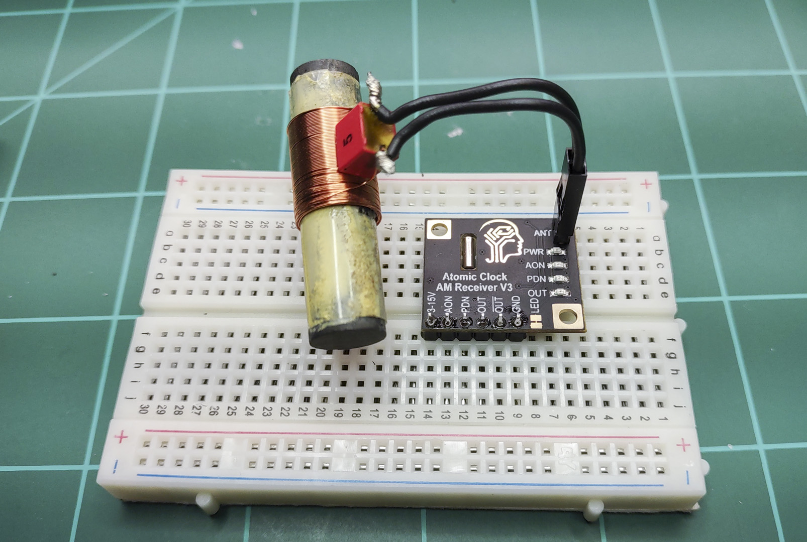
I have finally gotten around to wrapping up my driver for the Canaduino 60kHz WWVB clock receiver breakout board I purchased last fall.
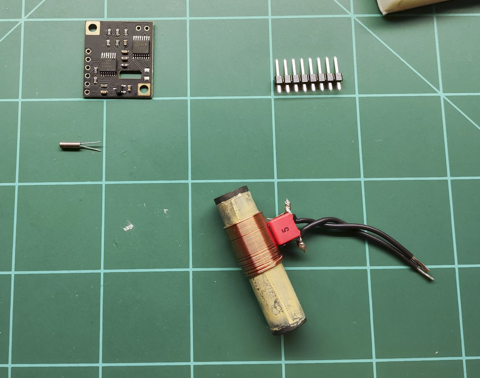
Information on assembling and testing the breakout board can be found here.
In that post I discuss the post written by Bruce E. Hall, W8BH. (I’m going to assume you understand his post well – my post will not explain any of the format of the data coming in, just how I process it). His post is a great explanation of using the breakout board and includes code to access it. Mr. Hall ends up writing interrupt based code to read the board. Unfortunately his code to find the beginning of the packet (a function called sync) is blocking code (e.g. nothing else can run while it is running). If you can’t get a clean signal quickly (almost always the case, at least for me), then the code still spends a lot of time in sync and blocking.
For the breakout board to meet my needs, it can’t be blocking any other code I want to run. So I decided to try and write my own Atomic Clock receiver interrupt routine that could perform the entire process of finding the start of a data packet and then retrieving and decoding it.
My code ONLY runs on a Teensy 3.x or 4.x microcontroller. It was my intention to write it to also run on an Arduino Nano, but I quickly found I did not have enough memory for it to run on a Nano. Except for the interrupt timer, the rest of the code is pretty vanilla so it probably would not be too hard to migrate to another MCU with more memory.
The interrupt routine was interesting to write. I’ve written interrupt routines before but nothing this large. In essence, it is a small program that runs constantly in the background trying to receive a good time packet while allowing the rest of the code to run unmolested.
The main code (loop()) is written as a state machine. The interrupt routine (wwvblib) is also written as a (finite) state machine. Prior to working with MCUs, maybe I ran across the definition of a state machine, but I never had any reason to implement one.
Once I started working with MCUs I struggled trying to handle interactions with the outside world reliably. I was then introduced to state machines. I remember seeing a state machine for a vending machine, and it was an AHA! moment. It had always been a mystery how a largely mechanical device could count change. Once I started using the state machine concept, I started being able to write much more bullet-proof MCU code.
The Library
The library and test code can be found here.
The wwvb library is in the files wwvblib.h and wwvblib.cpp. Those will also need globals.h and globals.cpp to provide some generic types and procedures I use across all these files.
The rest of the modules make up the code used to test the wwvblib.
I do not believe any other externals, other than those installed when Teensyduino is installed, are required to compile this code.
Operation of the Test Code
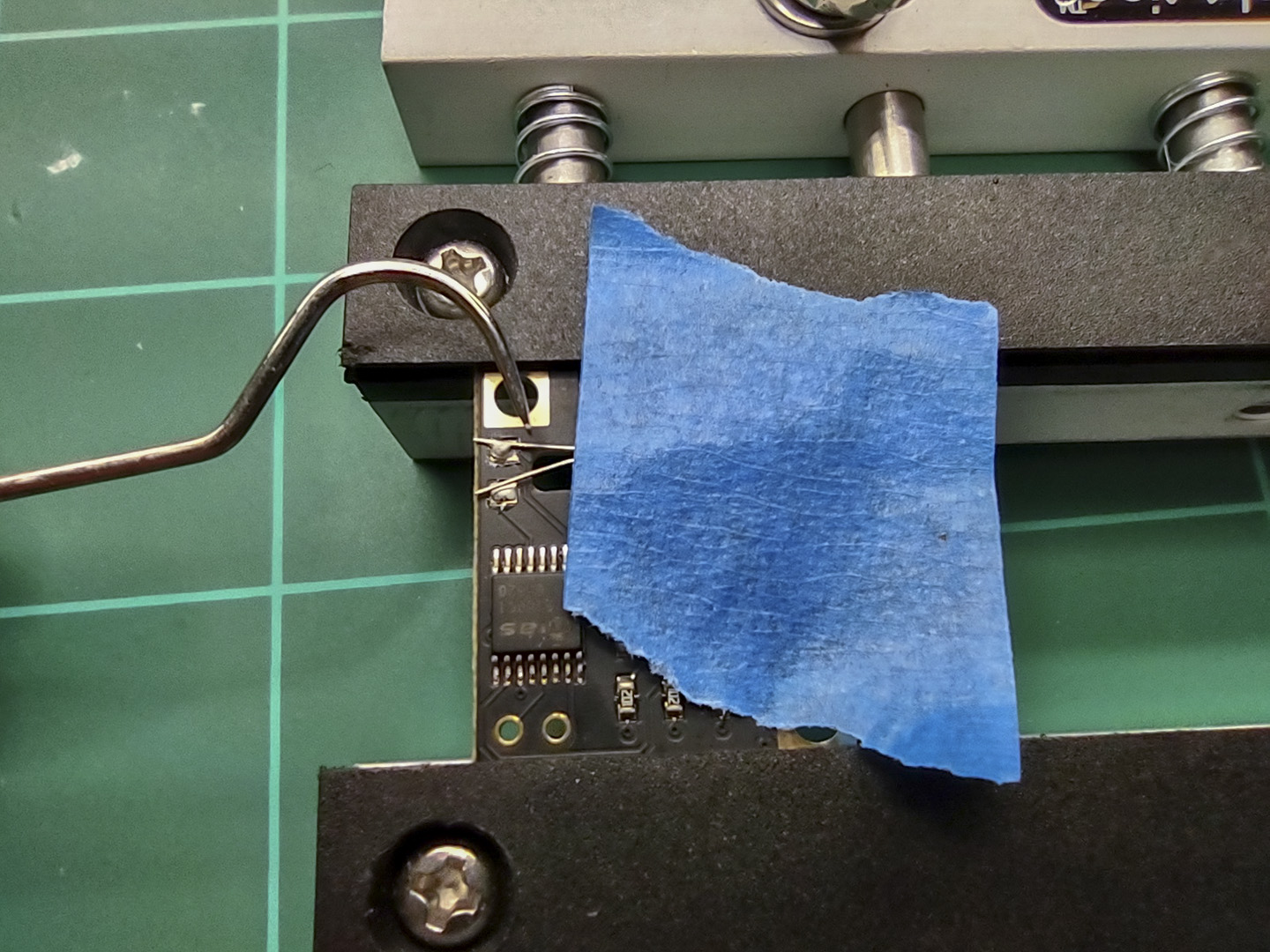
The hardware should be setup as described here with the breakout board pin OUT connected to pin 3 on the Teensy 4.x or pin 20 on the Teensy 3.x.
With the breakout board connected to the MCU, compile the code and connect to the MCU serial port with a terminal emulator configured for 9600 baud. You will see:
@loop
@STATE: st_init
@ti_init: tz: 3; useDLS: 1; timeStatus: 2
now(): 02/02/2024 08:55:41; ti_DLS: 0
@wwv_init: 02/02/2024 08:55:41; startHour: 0; duration: 0

Press any key to monitor signal strength.
Unless you just happen to have a strong signal, the code will do nothing else.
The first thing you can do is press a key to enable the signal strength monitor. This can help you align the antenna to get the best signal. When press any key you will see:
@STATE: st_idle_init
@STATE: st_sigStrength
Press any key to stop monitoring signal strength.
@wwv_sigStrength (08:55:57): Trans: 7; T/sec: 2; f: 1.000; Strength: 9
@wwv_sigStrength (08:56:00): Trans: 13; T/sec: 4; f: 0.958; Strength: 8
@wwv_sigStrength (08:56:03): Trans: 5; T/sec: 2; f: 1.000; Strength: 9
@wwv_sigStrength (08:56:06): Trans: 6; T/sec: 2; f: 1.000; Strength: 9
@wwv_sigStrength (08:56:09): Trans: 4; T/sec: 1; Strength: 10
@wwv_sigStrength (08:56:13):
Done Monitoring.
The signal strength is reported as the last datum on each line. Rotating the antenna you will see the strength change. You MUST have a continual signal strength of 10 to receive valid data. That will normally only be the case at night, often for just a few hours.
Rather than wait for a good signal, you can emulate one using the procedure I outlined here. Note that I have had great luck using the emulator software on a tablet that has a stronger speaker than my phone. The procedure will work on my phone, but not as reliably.
Once the program sees the beginning of a packet, it will start reporting its progress of receiving and decoding the packet:
02/02/2024 08:57:59 2nd Marker found(59s)
Date & Time: 02/02/2024 08:58:00: ti_valid: 1
@readPacketInit_state
480 180 510 190 520 190 210 210 790 170 210 210 510 190 210 520 200 210 790 170
250 170 250 170 210 250 480 520 790 180 250 480 520 190 210 210 210 210 800 200
170 210 210 210 210 240 470 220 750 180 510 180 210 210 510 180 210 210 790
@readPacketDone_state:
MHLHLHLLLMLLLHLLHLLMLLLLLLLHHMLLHHLLLLLMLLLLLLLHLMLHLLLHLLLM
@decodeBits_state: 08:58:59
@ti_setRTC: timeStamp: 1706885940
Teensy internal RTC to Fri Feb 2 06:59:00 2024
old time : 02/02/2024 08:58:59(1706864339)
new time : 02/02/2024 06:59:00(1706857140)
correction: -7199
02/02/2024 06:59:00: decoded wwvb packet: 033/2024 14:58:00 GMT
DUT1 sign: 0; Offset: 0.000000; Leap Year: 1; Leap Second: 0; DST: 0
mo: 2; da: 2
timeStamp : 1706885940
wwv_corrLast : -7199
wwv_syncCount: 1
wwv_corrTotal: 0
wwv_corrAvg : 0.000000
packetRxTimer: 59820
Date & Time: 02/02/2024 06:59:00: ti_valid: 1
@waitForNextCycleInit_state: reqStartHour: 0
@ti_updDLS: time changed manually. Locking out ti_updDLS
In the above example, you will see the time is corrected a lot – 7199 seconds. This was because the Teensy’s RTC (real-time clock) had been set 2 timezones different from what the test code was expecting (the RTC was set for CST and the test code was being run for PST).
wwvblib Calls
Note: I do NOT create objects in C++, thus this library doesn’t have any objects. Having used objects in Delphi/Lazarus for many years, I find C++ objects to be grotesque. You probably like them and that is fine. Just explaining why they aren’t present here…
There are just 3 calls necessary to use wwvlib:
wwv_init(<startHour>,<duration>)
Use wwv_init to initialized the process. When you call wwv_init, it will immediately enable wwv_tick (the function called by the timer interrupt), and start trying to get a good wwvb packet. Once a good time packet is received, then <startHour> / <duration> will control when wwv_tick will try again. <startHour> is the hour when it will start retrying. <duration> is how long it will try, in hours. The default is wwv_init(0, 6) which will start trying at midnight and try for 6 hours before giving up and waiting for the next midnight.
wwv_end()
You can call wwv_end at any time to stop wwvlib from trying to receive a good packet any longer by turning off wwv_tick.
int wwv_sigStrength()
wwv_sigStrength samples the OUT signal on the breakout board 100 times per second for 3 seconds. From this it will calculate the signal strength from 0 to 10 and return that value to you.
Supposedly, wwv_sigStrength will not impact the interrupt procedure (wwv_tick) which might also be trying to decode simultaneously. In practice, it seemed to me that it was interfering with wwv_tick.
There are several global variables you can read
wwv_abortCount – number of times wwv_tick gave up because duration exceeded.
wwv_corrAvg – Average of all the corerections (seconds).
wwv_corrLast – the last correction (in seconds).
wwv_corrTotal – The total number of corrections.
wwv_decode – the last decoded wwvb packets.
wwv_timeSet – the time the RTC was last set by wwv.
wwv_state – state of wwv_tick: invalid, listening, valid.
wwv_syncCount – number of times the RTC has been set by wwv_tick.
Code Overview
firmware.ino contains setup() and loop() functions. Looking at it:
At the top are the compiler versions and board settings I used to compile the code.
As mentioned earlier, firmware.ino is implemented as a very simple state machine. The init state starts everything up. It then moves to the idle state which primarly just displays the current time every minute and waits for the user to press a key. If a key is pressed, sigStrength is entered which will continuously report the signal strength until another key is pressed.
globals.h contains a couple of config macros you will probably want to change:
#define rtcTeensy // RTC internal to Teensy 3x/4x
//#define rtcDS3231 // External DS3231 RTC
//#define rtcNone // No RTC available
The Teensy 4.x has a built in RTC (real-time clock). If you are using it, define rtcTeensy to make use of it.
The Teensy 3.x has an RTC, but requires a crystal be soldered to the board for it to function. If you have the crystal, use #define rtcTeensy. Otherwise, you can use an external DS3231 RTC or not use one at all (in which case the date/time is invalid when the Teensy 3.x starts and until it properly receives a packet from the breakout board.
wwvblib is where everything happens. Actually, wwv_init and wwv_end are very simple. They simply setup/teardown a timer interrupt that will call wwv_tick every 10ms. So, really, wwv_tick is where everything happens.
wwv_tick is implemented as a state machine. When the timer interrupt calls wwv_tick, it will execute which ever state is in the <state> variable. That state may or may not change the <state> variable, but, either way, once the current state is completed, wwv_tick is exited and the process starts over again on the next timer interrupt.
Note that there are quite a few variables in wwvlib.cpp declared static so they will retain their value between calls by the timer interrupt.
The states of wwv_tick (found in the <state> variable) are:
init_state – Setup to start looking for the beginning of a packet (2 adjacent MARKs).
getMark1_state – this state examines the breakout board OUT pin for a MARK signal. It waits for a HIGH signal then determines what type of signal it read. If a MARK is found, <state> is set to getMark2_state otherwise it is set to init_state.
getMark2_state – if a 1st MARK is found, then this state looks for the next bit read to also be a MARK. Two adjacent MARKs indicate the beginning of the packet has been found. If 2nd MARK is found, <state> becomes readPacketInit_state otherwise the <state> returns to init_state.
readPacketInit_state – we’ve found the beginning of a packet so setup to read it and then proceed to readPacket_state.
readPacket_state – This state will read all of the bits to create a buffer of the entire packet. If any error is detected, <state> returns to init_state. If we read all 60 bits, then <state> becomes readPacketDone_state.
readPacketDone_state – The packet has been read. This state will do some simple tests to verify a good packet. If good, <state> becomes decodeBits_state otherwise <state> becomes init_state.
decodeBits_state – This is a lengthy state that decodes every bit in <packet>, creating the proper values in wwv_decode. Once the packet is decoded, this state also sets the RTC using values decoded into wwv_decode. If an error is detected by this state, <state> is set to init_state otherwise it is set to done-state.
done_state – This state does a bit of cleanup, then proceeds to waitforNextCyleInit.
timeout_state – This state is entered only if <duration> is exceeded. A bit of cleanup occurs, then this state proceed to waitForNextCyleInit_state.
waitForNextCycleInit_state – This state determines if we need to wait until <startHour> to start another cycle or if we should start trying to receive another packet immediately. It wil either proceed to init_state or waitForNextCyle_state.
waitForNextCycle_state – This state pauses wwv_tick until <startHour> occurs.
The states of wwv_tick do a pretty good job of describing how the beginning of a packet is found, read, decoded, and processed. The one thing I don’t mention is how I try to handle noise.
<recentBits> is used to ignore short drops in a HIGH signal. wwv_tick looks at the radio signal every 10ms waiting to find a HIGH signal. Once a HIGH signal is seen, a timer (<timer>) is started and wwv_tick keeps sampling the radio signal. Now, however, instead of just looking for a single LOW signal, it waits until it samples 4 LOW signals in a row.
<recentBits> always contains the last 4 samples read from the breakout board. Only when the last 4 samples are LOW (<recentBits> == 0) does wwv_tick assume it really has encountered a LOW signal. Once that 4 LOW signals have been sampled in a row, then 40ms is subtracted from <timer> (10ms per LOW signal read), and <timer> now contains how long the HIGH signal lasted. Thus, spurious LOWs in the middle of a long HIGH are ignored.
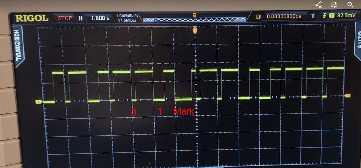
Once the signal transitions from HIGH to LOW we can look at the value of <timer> to determine if we received a LOW, HIGH, or MARK bit. Per the MAS6180C datasheet the timer range for each is:
100-300              LOW
400-600              HIGH
700-900              MARK
What’s Next?
I’ve implemented this code on my Teensy 4.0 Dev platform which includes a WiFi module. I can obtain current time from either an NTP source or the WWVB radio station. Along with the Teensy RTC maintaining time when there is no power, I’ve created a pretty accurate clock.
Originally I was going to use this to drive a Nixie Tube display. But then I was given an old Simplex commercial clock (like found in schools at least when I went to school). I would like to place that Simplex clock in my lab.
Now my plan is to figure out how to force that clock to sync and use this project to then maintain accurate time on that old clock.

 I removed the carb and played with it. Clearly, the valve was not closing all the way, but there was nothing wrong with the linkage. The pin in the thermowax actuator was fully retracted, but the butter fly valve would open as I placed the carb back into position. It was like the thermowax actuator was just too long:
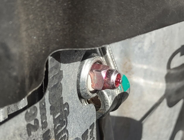 I sent this picture to my friend who said it definitely was sticking out too far and sent this video to me for reference:
 With the putty out of the hole, now the actuator fits properly:
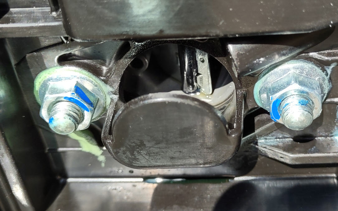
 and the choke butterfly valve fully closes:
 Note to anyone having this problem: above is exactly how the butterfly valve should look when the engine is cold. When this problem started, I tried repeatedly to find a picture of what this valve should look like closed so I could verify I was having a choke issue. I never found a clear picture and was never quite sure if the choke was the problem until now.